Навигация по сайту
- Игры / Образы
- Игры на русском языке
- Коды / Советы / Секреты
- Наши переводы
- Наши проекты
- Игры на русском языке (OnLine)
- Эмуляторы
- Обзоры игр
- Информация
- Статьи
- Интервью
- Мануалы / Инструкции
Случайная игра
Вступай!!!
Облако тегов
Показать все теги
1. Introduction
A video game console is a computer designed primarily for playing video games. As technology progresses, video game consoles are made progressively better and capable of running ever more realistic games. As this happens,
old consoles are made obsolete and become unsupported, thus making it increasingly dicult to experience old games.
One solution to this inconvenience is the practice of emulating old consoles using emulators. A video game emulator is a piece of software designed to emulate the workings of a video game console well enough to make it possible
to run games designed for that console on a di erent system - usually a personal computer or a modern console.
Fans also use emulators to run video game modi cations unapproved by the manufacturers of the console, such as fan translations and hacks.
Another use of emulators is to aid in the development of games through enhanced debugging and the convenience of reducing friction in the builddeploytest cycle by testing on the same machine where development happens.

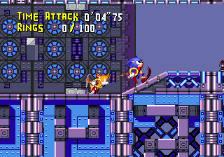
Figure 1: Sonic the Hedgehog running in the Kega Fusion emulator
2. Emulation
Most computers produced after the 1940s implement the Von Neumann architecture (Fig. 2), which consists of a processing unit (CPU), memory and input and output mechanisms. These subdivisions share a common bus, a subsystem that transfers data between components.

Figure 2: Von Neumann architecture
An emulator has to emulate all of the components of a computer architecture as well as their interoperation. An example of such an architecture is the one implemented in Sega Genesis, a console popular in the early 1990s. The
architecture, as shown in Fig. 3, consists of two general-purpose processors, three Random Access Memory (RAM) devices, a Video Display Processor (VDP), a Sound processing unit, a Programmable Sound Generator (PSG),
input and output (I/O), peripherals and a replaceable cartridge that holds the program data. As some of the components are 8-bit and some are 16-bit, there are 8 and 16-bit buses and a bus arbiter. Each bus consists of a control, address and data buses.

Figure 3: Simpli ed Sega Genesis architecture
2.1 Accuracy
Although at rst glance it may seem like the best way to go about emulating each component is to emulate it as accurately as possible, accuracy comes at a signi cant cost in performance. Whether performance or delity is more
important depends on the requirements of a given emulation project.
The possible accuracy levels have been classi ed in into classes of decreasing accuracy:
Data-path Accuracy is the highest level of accuracy. Emulators in this class simulate the physical characteristics of a given component, down to the data-path level. This is mostly used in hardware development for prototyping integrated chips. Another use is historical preservation, as seen in the interactive Visual 6502 simulator which simulates a 6502
CPU down to the transistor level by working with digitized microscopic photographs of the CPU (Fig. 4). This is also the slowest method of emulating a chip; the Visual 6502 simulator runs at 27Hz on a modern computer, which at 2GHz is a slowdown by a factor of approximately 75 million.

Figure 4: Vectorized layers of the MOS 6502 CPU, courtesy of Visual6502
Cycle Accuracy forgoes emulating the precise workings of a chip, instead only requiring faithful emulation of the underlying Instruction Set Architecture (ISA) and the timings of instructions relative to each other.
Typically, precise timings are only required on old 8 and 16-bit architectures, where programmers could depend on the timings for certain e ects. An example is VICE which emulates Commodore 64 cycleaccurately.
Instruction-level Accuracy is concerned with accurately emulating instructions and their side e ects while ignoring their precise timing. This is a fairly common level of accuracy as it is a reasonable accuracy vs speed trade-o .
Basic-block Accuracy allows replacing larger blocks of code with native code equivalents. This method is faster than instruction-level accuracy but it does not allow single-stepping through code and does not work with code that relies on its original form, such as self-modifying code. The Amiga emulator UAE is an example.
High-Level (HLE) Accuracy identi es structures in code that can be replaced by native high-level functionality. Recent gaming consoles are often emulated by detecting audio and video library code calls and replacing them by native library implementations without ever executing the original library code. The UltraHLE Nintendo 64 emulator is
famous for being the rst emulator of this kind. At the time of its release, 1999, a mere 3 years after the release of the Nintendo 64, it ran commercial titles at a playable frame rate on the hardware of the time.
This approach had its drawbacks; at the time of release, UltraHLE was only able to emulate approximately 20 games to a playable standard.
Overall, faster emulation means less accuracy. Fig. 5 compares the speed of Visual 6502, VICE and UltraHLE. Some consideration should be given to undocumented CPU instructions, as games might depend on undocumented behavior.
| Emulator | Accuracy class | Speed | Slowdown factor |
|---|---|---|---|
| Visual 6502 | Data-path | 27Hz @ 2GHz | 75 million |
| VICE | Cycle | 2x1Mhz @ 500Mhz | 250 |
| UltraHLE | HLE | 93.75Mhz @ 350Mhz | 3.7 |
Figure 5: Speed comparison of three emulators from distinct classes
2.2 System emulation
Typically, to emulate the top-level logic of the architecture, a simple loop is used, as shown in Fig. 6. Each component is ran for a number of steps, usually equivalent to a fraction of a second, e.g. a frame (there are 50/60 frames in a second on a 50/60Hz display). Then, synchronization is performed between the various components.
while not finished:
for component in components:
component.run_for_some_time()
synchronize()
for component in components:
component.run_for_some_time()
synchronize()
Figure 6: Main emulation loop pseudo-code
Typically a computer system has one or more address buses, in which addresses and address ranges are assigned to components. For example, the Sega Genesis has two address buses, as shown in Fig. 7.
Memory mappings fall under two categories:
Linear mapping - a mapping where an address range is translated to a
corresponding physical address range and address lines are used directly
without any decoding logic, for example in accessing physical memory.
Direct mapping - a 1:1 mapping of a unique address to one hardware
register or a physical memory location.
| Device | Address (hex) |
|---|---|
| 16-bit bus | |
| Cartridge | 000000-3FFFFF |
| 8K RAM | A00000-A01FFF |
| Sound processor | A04000-A04003 |
| I/O | A10000-A1001F |
| VDP Data | C00000 |
| VDP Control | C00004 |
| PSG | C00011 |
| 64K RAM | FF0000-FFFFFF |
| 8-bit bus | |
| 8K RAM | 0000-1FFF |
| Sound processor | 4000-4003 |
| Bank register | 6000 |
| PSG | 7F11 |
| Banked memory | 8000-FFFF |
Figure 7: Simpli ed Sega Genesis address map
As seen in the Sega Genesis example (Fig. 7), memory maps often contain holes. For simplicity of circuit design, certain mappings are mirrored, for example on the Sega Genesis, the RAM address 1234 can be accessed by accessing both FF1234 and EF1234.
An emulator must decode all memory accesses according to the appropriate memory map.
Components send signals called interrupts, of which there are two types.
A hardware interrupt is a signal from a component indicating it needs attention.
A software interrupt is a CPU instruction. When a CPU receives an interrupt, it suspends its current state of execution and begins execution of an interrupt handler. This usually invokes an exception appropriate to the
kind of interrupt.
Interrupts are typically used for signaling from components, timers and traps (user interrupts). A simpli ed exception table for the main CPU in the Sega Genesis system is shown in Fig. 8. On the Genesis, the VDP res a Vertical Blank interrupt every vertical blank, which occurs at the start of every displayed frame (50 times a second on a PAL TV and 60 on an NTSC TV), which is useful for timing-dependent functions. The VDP also signals a Horizontal Blank interrupt every horizontal blank, which occurs after a line has been displayed (about every 10 μs). Finally, there is an external interrupt, used for example to tell the game a light gun has been red.
| Type | Number | Exception |
|---|---|---|
| Reset | 0 | Reset Initial Stack Pointer |
| 1 | Reset Initial Program Counter | |
| Errors | 2 | Access Fault |
| 3 | Address Error | |
| 4 | Illegal Instruction | |
| 5 | Integer Divide by Zero | |
| Traps | 6 | CHK Instruction |
| 7 | TRAPV Instruction | |
| 8 | Privilege Violation | |
| 9 | Trace | |
| 10 | Line 1010 Emulator | |
| 11 | Line 1111 Emulator | |
| Interrupts | 24 | Spurious Interrupt |
| 25 | Level 1 Interrupt (Unused) | |
| 26 | Level 2 Interrupt (External) | |
| 27 | Level 3 Interrupt (Unused) | |
| 28 | Level 4 Interrupt (Horizontal Blank) | |
| 29 | Level 5 Interrupt (Unused) | |
| 30 | Level 6 Interrupt (Vertical Blank) | |
| 31 | Level 7 Interrupt (Unused) | |
| Traps | 32-47 | Trap #0-15 Instructions |
Figure 8: Sega Genesis exception vector table for the 68000 CPU
2.3 CPU emulation
describes three approaches to emulating CPUs: interpretation, recompilation and a hybrid method.
2.3.1 Interpretation
Interpretation is the simplest way of emulating a CPU. As shown in Fig. 10, an interpreter directly simulates the fetch-decode-execute cycle (Fig. 9).
That is, until the emulator is shut down, it fetches the next instruction,
decodes and executes it.

Figure 9: Fetch-decode-execute cycle
Interpretation is slow, as for every original instruction a couple dozen native instructions are executed. Additionally, modern CPUs take advantage of a technique called pipelining, which allows them to execute many instructions at once, as long as it is possible to predict what instructions will be called in advance. A simulated fetch-decode-loop makes predicting future instructions impossible, thus modern CPUs are often unable to use pipelining in interpreter code.
2.3.2 Recompilation
Recompilation translates emulated code to native code. It takes advantage of the fact that it is unnecessary to decode instructions every time they need
while not finished:
# fetch
instruction = memory[IP]
IP += 2 # increment the instruction pointer register
# decode
if instruction == 0x4e71:
# execute NOP instruction
pass
else if (instruction >> 8) == 0:
# decode and execute an ORI instruction
# decode the appropriate effective address
size = (instruction >> 6) & 3
ea_mode = (instruction >> 3) & 7
ea_register = instruction & 7
ea = get_ea(ea_mode, ea_register, size)
# OR the effective address by an immediate value
*ea |= get_immediate(size)
set_flags()
else if (opcode >> 8) == 1:
...
Figure 10: 68000 CPU interpreter pseudo-code
to be executed, and moves the decoding part to the pre-processing phase of the emulator.
Threaded recompilation is the simplest form of recompilation, as it simply replaces each original instruction with a library call to a native code implementation of the original instruction. An example translation can be seen in Fig. 11.
Real recompilation, on the other hand, translates original code into native code directly, without the need for instruction function calls.
Recompilation can be done ahead-of-time (AOT), i.e. before execution or just-in-time (JIT), i.e. during execution.
move.w #7, d0 move(1, 7, 0)
addi.w d1, d0 addi(1, 1, 0)
ori.w #1, d0 ori(1, 1, 0)
ori(size, source, dest):
d[dest] |= d[source]
set_flags()
addi.w d1, d0 addi(1, 1, 0)
ori.w #1, d0 ori(1, 1, 0)
ori(size, source, dest):
d[dest] |= d[source]
set_flags()
Figure 11: Sample 68000 code and resulting threaded code (pseudo-code)
2.3.3 Static recompilation
Static recompilation is ahead-of-time recompilation. A statically recompiled program is indistinguishable from a native program and does not contain any translation logic.
Like normal ahead-of-time compilers, static recompilers can perform global optimizations on programs, resulting in fast execution time. This comes at a cost, however, as static recompilation is a hard problem. Programs on Von Neumann architectures frequently intertwine code and data and recognizing what is code and what is data might be hard or impossible, depending on the architecture.
To illustrate this, a jump table, as shown in Fig. 12, is a piece of code that loads an address based on an index and then jumps to it. In the example, if index holds the number 0, the code will jump to Level and if index holds 1, the jump will be to Title.
The problem is, a recompiler does not know how many entires there are in the jump table. So it can't know that 02427fff (the machine code representation of the andi.w instruction) is an instruction and not an address to jump to.
move.w (index).w,d0
lsl.w #2, d0; d0 = d0*4 (addresses are 4 bytes long)
move.w JumpTable(pc,d0.w),d0
jmp JumpTable(pc,d0.w)
JumpTable:
dc.l Level
dc.l Title
dc.l Ending
dc.l Credits
andi.w $7FFF,d2; machine code = 02427fff
...
lsl.w #2, d0; d0 = d0*4 (addresses are 4 bytes long)
move.w JumpTable(pc,d0.w),d0
jmp JumpTable(pc,d0.w)
JumpTable:
dc.l Level
dc.l Title
dc.l Ending
dc.l Credits
andi.w $7FFF,d2; machine code = 02427fff
...
Figure 12: Example 68000 assembly jump table
Video games up until the 1990s were often written in assembly, and used techniques harmful to static analysis, such as self-modifying code. Some seemingly harmless practices, such as decompressing, decrypting or loading code into memory are basically equivalent to self-modifying code for recompilationpurposes.
These issues make it difficult to write a completely accurate static recompiler that is oblivious to the input code, but often such characteristics are unnecessary. If only a single game is needed to be recompiled, it suffices to play through the game completely, logging what is code and what is data with an interpreting emulator and then to perform static recompilation.
2.3.4 Dynamic recompilation
A dynamic, or just-in-time (JIT) recompiler translates original code to native code on the y and then caches the resulting native code for later execution.
Although translation of a single piece of code is more computationally expensive than interpretation, most of the execution time in a program is usually spent in relatively small loops. A JIT recompiler only has to translate a loop once, but it can run the loop thousands of times, so for an average program this is an overall speed improvement.
JIT recompilers do not have to possess advance knowledge of what is code and what is data, since only valid code paths will be translated. JIT also solves the problem of self-modifying code. If a code modi cation is detected, the code can be marked as dirty for later recompilation. For this and for the speed improvements, JIT recompilers are popular in modern emulators.
2.3.5 Hotspot method
The hotspot method, rst used in the eponymous HotSpot Java virtual machine, aims to combine the best of both worlds, the speed of interpreters in rarely executed code and the speed of JITs in often executed code.
It does so by interpreting by default and identifying hot spots, that is, oftenrun code and marking it for recompilation. This is best seen by examining the cost formulas in Fig. 13. The average cost per execution is visualized in Fig. 14, in which it can be seen that for typical values of ce, ci and cr (2, 10 and 50 respectively) the hotspot method approaches dynamic recompiling in terms of cost for often executed code, while maintaining the fast speed of
interpreting code that is only run once.
2.4 Graphics emulation
Graphics and music hardware is varied and it is impractical to enumerate all of the di erent variations - it suffices to introduce the more common and general concepts used. Once the functionality of the given hardware is known, it is a fairly straight-forward process to emulate it. Optimization of emulation depends largely on speci c components used.
A video display (such as a TV) displays graphics composed of pixels and

where

Figure 13: Cost formulas for an interpreter, a dynamic recompiler and the hotspot method
refreshes at a speci c rate (typically 50 or 60 times per second). A pixel is the smallest controllable element of a picture. A game console processes graphics and then sends them to the video display at a speci c resolution. For example, the Sega Genesis is capable of outputting 240 lines each consisting of 320 pixels (this is typically referred to as a resolution of 320x240). Video game consoles usually have a distinct video output device which processes graphics and outputs video signal.
2.4.1 Framebu
ers
The simplest video output device is the framebu er, which drives a video display from a memory bu er containing a complete frame of data.
The memory bu er consists typically of color values for each pixel on the screen. The number of values each color value can take is the color depth, and this is the number of colors the device can display simultaneously. The bigger the color depth, the more bits it takes to store a single color value, and

Figure 14: Average cost graph for di erent emulation methods
in turn, the more memory is needed to store the frame bu er. For example, a 24-bit 800x600 frame bu er needs 800 * 600 * 24=8 = 1440000 bytes, or 1:4 megabytes of memory, while a 4-bit one with the same resolution only needs 800 * 600 * 4=8 = 240000 or 234 kilobytes of memory.
In order to save memory and storage, a technique called indexed color is used where instead of a full color bu er, an indexed bu er is used. With this technique, color information is stored in a bu er called a palette in which every color is indexed by its position in the palette. Instead of full color values, an indexed bu er stores palette indexes for each pixel. An example indexed image in 1, 2 and 8-bit color depths is shown in Fig. 15. As shown in Fig. 16, this method was used in numerous systems. For example, the Sega Genesis has a palette that can hold up to 64 di erent colors selected from 512 di erent color values.

Figure 15: 1, 2, 8-bit indexed color pictures and original 24-bit color picture
2.4.2 Tile-based graphics
To save memory and storage even more, instead of directly controllable framebu ers some systems implemented a tile-based method of storing graphics data in memory. Using this method, screens are composed of tiles instead of individual pixels. In turn, the tiles are composed of pixels or even smaller tiles. This is illustrated by Fig. 17. The video hardware composes the tiles on the
y in each frame or line instead of keeping it in memory. This approach made it possible to reuse frequently occurring tiles, such as the sky, empty space and other repeating patterns.
As an example, in the Sega Genesis, the screen was composed of two main tile planes and one auxiliary plane. The main planes could hold 4096 tiles
| Color depth | Number of colors | Used in |
|---|---|---|
| 1-bit | 2 | Atari ST |
| 3-bit | 8 | ZX Spectrum |
| 4-bit | 16 | Amstrad CPC |
| 6-bit | 64 | Sega Genesis |
| 8-bit | 256 | Atari TT, AGA, Falcon030 |
| 11-bit | 2048 | Nintendo SNES |
| 12-bit | 4096 | Neo Geo |
| 15-bit | 32768 | Sega Saturn |
Figure 16: Indexed color depth used in a number of systems
each. Each tile was 8x8 pixels and video memory could hold approximately 1300-1800 distinct tiles at a time. Each tile could be displayed in one of four palette lines, further promoting reuse of tiles. Fig. 18 shows the planes that the screenshot in Fig. 17a is composed of.
2.4.3 Sprites
Apart from backgrounds and foregrounds, objects (such as the player character, enemies and items) were a common occurrence in video games. Unlike backgrounds and foregrounds which typically t well into tile-based graphics,
objects could move in arbitrary ways, making tiling difficult. Because of this, consoles used to incorporate sprites into their video graphics hardware.
Generally, sprites are bitmaps which can be moved on the screen without altering the data de ning the rest of the screen. This introduced considerable space and bandwidth savings, as instead of modifying the entire a ected area of the screen every time an object was to be drawn, the game only had to send a small sprite frame to the graphics hardware. This was useful for animated objects as only the sprite frame had to be changed in an animation. Fig. 19 shows distinct frames of a sprite that appears in the frame in Fig. 17a.

(a) Frame

(b) Tiles in video memory
Figure 17: Screenshot of the game Ristar and tiles in video memory at the time
Implementing sprites in the hardware was an opportunity to relieve software from doing some work that is common to working with sprites. One such example is scaling and rotation, which was implemented on the Game Boy Advance system. A common feature was to perform collision detection, as the spriting hardware already had all the sprite position information. An overview of sprite hardware capabilities for several systems is shown in Fig. 20.
2.4.4 Vector displays
A vector display was a display device in which the image was composed of drawn lines instead of a grid of pixels. The electron beam would follow an

(a) Foreground plane

(b) Background plane

(c) Sprites plane
Figure 18: Planes of a single frame on the Sega Genesis

Figure 19: Sprite frames for an enemy in the game Ristar
arbitrary path tracing the connected lines, instead of following the standard
horizontal raster path. To utilize this kind of display, video hardware would
send commands directly to the electron beam, instead of image frames. The
video game console Vectrex was entirely based upon this concept. The popular
game Asteroid used vector graphics, as shown in Fig. 21
| Game Boy Advance | Neo Geo | Sega Genesis | SNES | |
|---|---|---|---|---|
| Sprites on screen Sprites on line Sprite size Colors Scaling Rotation Collision detection | 128 128 64x64 15, 255 Yes Yes - | 384 96 16x512 15 Shrinking - - | 80 20 32x32 15 - - Yes | 128 34 64x64 15 Limited Limited Yes |
Figure 20: Sprite hardware capabilities for several systems

[center]Figure 21: Screenshot of the game Asteroids
[/center]
2.4.5 Image scaling
Old video game consoles ran at much lower resolutions than screens today are capable of displaying. It is therefore necessary to upscale the image, which is a non-trivial task. The naive way of upscaling an image is to perform nearest-neighbor interpolation on the pixels. However this method is not very-well suited to the task, as its result looks jagged. There are a number of pixel art scaling algorithms designed speci cally to address this problem.
Fig. 22 compares several of them.
The first known algorithm is EPX. Developed to port LucasArts games to early Macintosh computers, which had about double the resolution of the original system. The algorithm replaces every pixel by a 2x2 block of the same color. Then, set the top left pixel in the 2x2 to the color of the left and upper neighbors of the pixels if their colors match and do the same for every pixel in the 2x2 block. Further magni cation can be obtained by running the algorithm several times.

(a) Nearest-neighbor

(b) EPX

(c) Super 2xSaI

(d) hq4x

(e) Kopf-Lischinski
Figure 22: Comparison of image scaling algorithms performed on a dolphin sprite from the game Super Mario World (4x magni cation)
A re nement on EPX is the Eagle algorithm, which works similarly but also considers pixels adjacent diagonally. A number of similar algorithms exist which di er in the way they calculate the resulting pixels but are similar in principle, such as 2xSaI [6], Super 2xSaI and Super Eagle. All of these algorithms su er from locality issues, as they only consider adjacent pixels.
A more sophisticated approach is used in the hqnx family of algorithms. First, the color di erence is calculated between the magni ed pixel and its 8 nearest neighbors. Then, that di erence is compared to a predetermined threshold to determine whether the two pixels are close or distant. Hence, there are 256 possible combinations of the closeness of the neighboring pixels. Second, a lookup table with 256 entries is used, one entry for each combination. Each entry describes how to mix the colors in the resulting image to interpolate pixels of the ltered image. As the most computationally intensive part of the algorithm is generating the lookup table, the algorithm performs very well in real time. Because of that, and because it delivers the best results when compared to other fast algorithms, it is used in numerous emulators, such as bsnes and FCE Ultra. Algorithms in the hqnx family still, however, su er from strict locality issues and cannot resolve certain ambiguities.
All of the algorithms presented so far su ered from locality issues. They also produce bitmaps and only work for predetermined degrees of magni cation. To address these problems, the Kopf-Lischinski algorithm was developed. It uses novel way to extract resolution-independent vector images from pixel images. The vector image can then be used to magnify the image by an arbitrary amount without feature degradation. The algorithm resolves features in the input image and converts them into regions with smoothly varying shading that are separated by piecewise-smooth contour
curves. Although it produces some of the best-looking results, the algorithm is quite complex and it is uncertain how it would perform in a real-time setting, as it has never been used in an emulator to date.
2.5 Sound emulation
2.5.1 Sampling
2.5.1 Sampling
Sound hardware typically processes digital audio and then performs digitaltoanalog conversion and outputs the analog signal. Sound waves are continuous signals and to process them digitally it is necessary to convert sound
waves to a discrete signal. A process called sampling takes measurements of a continuous signal at regular intervals and produces a set of digital samples, as shown in Fig. 23. An example sample is shown in Fig. 24.

Figure 23: Sampling of a simple sine wave. Samples are the black dots.
The simplest sound processing was to store samples and use them directly to generate sound. The Nyquist sampling theorem states that it suffices that

Figure 24: Sample of rain, thunder and chirping birds and a 0.1 second excerpt
of the sample
the sampling frequency is at least twice the wave's frequency for the analog signal to be completely determined by the sampling. Because the higher end of the range of human hearing is approximately 20kHz and for technical reasons, sound is typically sampled at 44.1 kHz, a bit above double 20kHz.
This means that to store a single second of 8-bit mono sound, 44100 bytes are needed, which was quite prohibitive when every single kilobyte mattered.
As with graphics, space and bandwidth concerns meant chips for generating sound on-they had to be developed. One type was the programmable sound generator, which generated sound waves by synthesizing several basic waveforms and combining them. Often PSGs would have a noise generator, to generate explosion and percussion sounds. An example is the SN76489 chip used in the Sega Genesis. As PSGs needed very few bits of input data to operate, they were used in the years before memory became large and a ordable enough to store sound samples. The downside of PSGs was that the sound generated was rather bland.
2.5.2 Frequency modulation
A very popular technique called frequency modulation was used to generate better sounding audio. The equation for a frequency-modulated wave of peak amplitude A is

An arbitrary modulating function f(t) is multiplied by the modulation (change) index I and added to the angle (Wc) of the carrier sine wave. In the case that the modulating wave is also a sine wave, the equation becomes

To create realistic sounding instruments, operators are used, each possessing a frequency, an envelope and the capability to modulate its input using the frequency and envelope. Operators are arranged in circuits. Several such circuits are shown in Fig. 25 and the instruments they mimic are listed in Fig. 26. To simulate chords, multiple FM channels are used.
This method was so pervasive in the 80s and early 90s that the patent Stanford licensed to Yamaha for the method generated over $20 million for the university in licensing fees alone before it expired in 1994, making it the second most lucrative licensing agreement in Stanford's history to that date [33].
An example of a frequency modulation synthesis chip was the Yamaha YM2612 which was used in the Sega Genesis and a number of arcade systems. It was capable of six concurrent FM channels, using four operators per channel (as shown in Fig. 25). One of the channels could be set to play digital samples instead [20].

Figure 25: FM operator circuits in the YM2612 chip
2.5.3 Aliasing
Typically, in sound hardware, the generated sound was fed to the speakers. An emulator, however, simulates the generation of sound and then stores the result in a sample. This results in aliasing, as harmonics above the Nyquist frequency of the sample (half the sample rate) will fold into the audible range, resulting in rough-sounding aliases. The solution to this problem is to perform band-limited synthesis.
Circuit (a)| distortion guitar, bass
Circuit (b)| harp, PSG-like sound
Circuit (c)| bass, electric guitar, brass, piano, woods
Circuit (d)| strings, folk guitar, chimes
Circuit (e)| ute, bells, chorus, bass drum, snare drum
Circuit (f)| brass, organ
Circuit (g)| xylophone, vibraphone, snare drum, tom-tom
Circuit (h)| pipe organ
Circuit (b)| harp, PSG-like sound
Circuit (c)| bass, electric guitar, brass, piano, woods
Circuit (d)| strings, folk guitar, chimes
Circuit (e)| ute, bells, chorus, bass drum, snare drum
Circuit (f)| brass, organ
Circuit (g)| xylophone, vibraphone, snare drum, tom-tom
Circuit (h)| pipe organ
Figure 26: FM operator circuits in Fig. 25 and instruments they are supposed to mimic
2.6 Documentation
As discussed before, in order to emulate a speci c system, the emulator has to emulate all of the components and also the system itself, therefore information is needed on how they operate is needed. For publicly available components such as most CPUs and popular video and sound chips, there is usually ample technical documentation available from the manufacturer.
However for proprietary components (such as the lockout chip on the Nintendo SNES), peripherals and the inner workings of the system the only primary documentation is usually con dential and not always possible to fi nd. Therefore reverse engineering is sometimes necessary.
Another source of information is the source code of many open source emulators, particularly the MAME project [19], whose stated goal is to be a reference to the inner workings of various arcade systems, and its sister project, MESS which does the same for console systems. Although the licenses for the projects are incompatible with commonly used free software and open source licenses and therefore their source code cannot be mixed with commonly-licensed code, they serve as secondary documentation for systems they emulate.
3. User interface
There are a number of enhancements to be made in an emulator. One of these is save states, which is a method of saving game progress for later use. Save states are snapshots of the machine state in a given moment. Because this approach is hardware-level, it makes it possible for the user to save their progress even in games which do not directly support it.

Figure 27: Cheat engine in the VisualBoyAdvance emulator

Figure 28: Debug mode in the Gens emulator
A common feature in emulators is the cheat engine, as seen in Fig. 27. It allows the user to nd memory addresses of in-game variables and modify them. This facilitates cheating, as one can, for example, modify the amount of money the player character has.
Some emulators implement a debug mode, where users can view and sometimes modify the internal state of the machine, as seen in Fig. 28. This is especially helpful to ROM hackers and homebrew game developers.
Author: Lukasz Zapart.
Вернуться
- Комментарий: 0
- Просмотров: 6866